KTAG help file: BOSCH EDC17 ECUs for Ford vehicles. This will be of great help to those here that want
to do read/write Ford ECU EDC 17 with K-tag programmer from China.
Warnings
To use this protocol of communication you have to remove and open the ECU. It is a risky operation, to
be done with great care and caution to avoid damaging the ECU beyond repair.
After opening the ECU and before proceeding with reading and/or programming, you are strongly advised
to reconnect the unit to the vehicle and start the engine, to make sure it still works.
To use this protocol you also need to connect to the ECU connector through a cable, and solder one or
more wires to the programming pads.
Incorrect or poorly made connections and solderings may damage the ECU, often beyond repair.
Under no circumstances we shall be liable for any damage caused to the ECU during the opening, due to
connections and soldering that do not comply with the instructions provided in this manual.
BY USING THIS PROTOCOL, YOU CONFIRM YOUR FULL AND UNCONDITIONAL ACCEPTANCE OF THIS TERMS AND
CONDITIONS, YOU RELIEVE US FROM ANY RESPONSIBILITY AND RENOUNCE TO ALL RIGHTS TO CLAIM ANY
COMPENSATION.
Notice
When writing the modified file, the checksum of the data may last several minutes, depending on the
performances of your computer.
Recommendation
1.Remove the ECU from the vehicle;
2.Open the ECU, taking care in not damaging the parts inside;
3.Reconnect the ECU to the vehicle and start the engine, in order to make sure that it is still
working and has not been damaged in the opening;
4.Remove again the ECU from the vehicle;
5.Select the right plug-in;
6.Always make a backup copy of the ECU before Reading and / or Writing.
Instructions: How to use KTAG Master for Ford EDC17
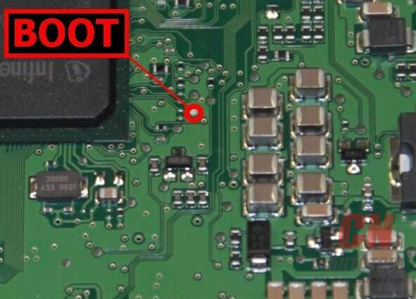
Step 1: Connect to the ECU according to the pinout provided for each model
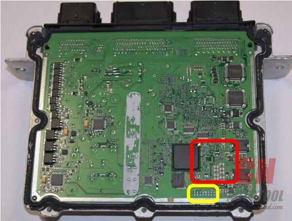
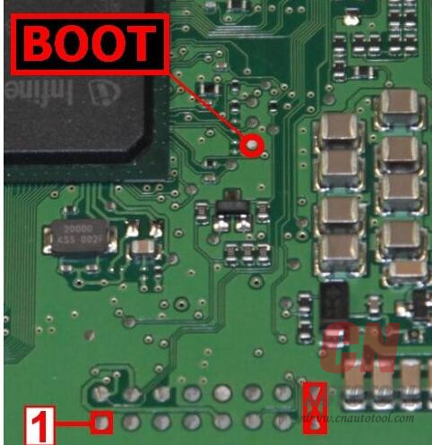
The pins Boot can be found on the right side of the ECU (in red in the picture).
The programming pads where to set the board adapter are located at the bottom right (in yellow).
♦ Plug-in 197: EDC17 CP05 XROM TC1796
Available connection mode:
♦ Connection using positioning frame and upper illumination deck
♦ Connection using only the positioning frame
♦ Direct connection
♦ Connection using positioning frame and upper illumination deck
Material needed:
Infineon Tricore module 14P600BTLR
AC Adaptor 1400SWALIM
Positioning frame 14P800ADBO complete with upper illumination deck and programming probes
Adapter 14P600KT04
Ribbon cable 14P600KT03
Connect the Tricore module 14P600BTLR to the tool;
Set the ECU on the positioning frame 14P800ADBO;
Connect the AC Adaptor 1400SWALIM to the upper illumination deck and the Tricore module;
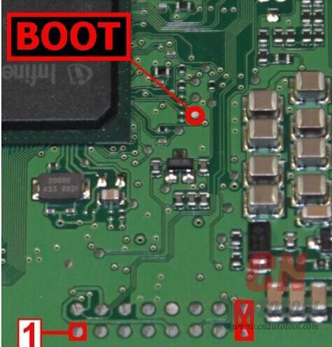
Set the adapter 14P600KT04 into the compartment of the frame and lower it on the ECU, starting from
Pin 1 marked in the picture;
Place a programming probe 14P800ABD3 on pin Boot shown in the picture, and wedge it under the deck.
Notice: Please refer to the positioning frame manual 14P800ADBO for an example of how to place the
programming probe 14P800ABD3.
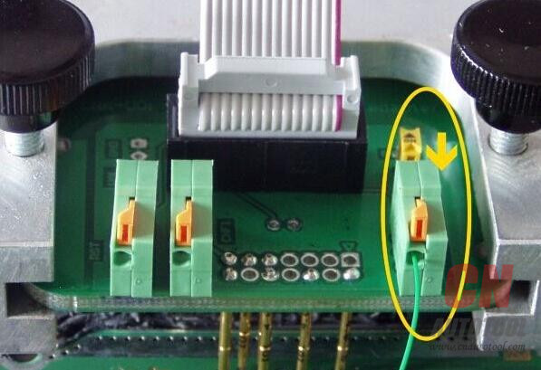
Ease the wire of the probe 14P800ABD3 into the BOOTD connector of the adapter.
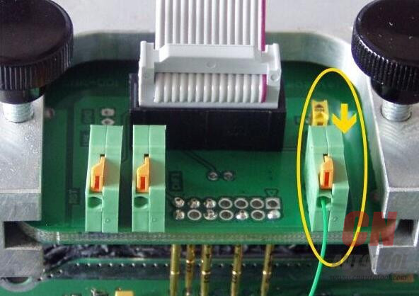
Notice: The adapter switch must be set to OFF as shown in the picture:
Connect the ribbon cable 14P600KT03 to the adapter and the Tricore module.
♦ Connection using only the positioning frame
Material needed:
Infineon Tricore module 14P600BTLR
AC Adaptor 1400SWALIM
Positioning frame 14P800ADBO
Adapter 14P600KT04
Ribbon cable 14P600KT03
Solder wire
♦ Pin Boot connected to the adapter
Connect the Tricore module 14P600BTLR to the tool and the AC Adaptor 1400SWALIM;
Set the ECU on the positioning frame 14P800ADBO;
Set the adapter 14P600KT04 into the compartment of the frame and lower it on the ECU, starting from
Pin 1 marked in the picture;
Solder a wire to pin Boot shown in the picture, and ease it into the BOOTD connector of the adapter.
Notice: The adapter switch must be set to OFF as shown in the picture:
Connect the ribbon cable 14P600KT03 to the adapter and the Tricore module;
Remove the soldered wire before re-installing the Auto ECU Programmer on the vehicle.
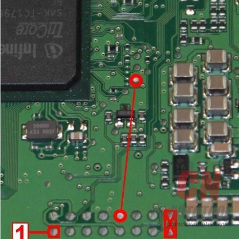
♦ Pin Boot soldered to the programming pad
Connect the Tricore module 14P600BTLR to the tool and the AC Adaptor 1400SWALIM;
Solder a bridge on the two programming pads shown in the picture:
Set the ECU on the positioning frame 14P800ADBO;
Set the adapter 14P600KT04 into the compartment of the frame and lower it on the ECU, starting from
Pin 1 marked in the picture.
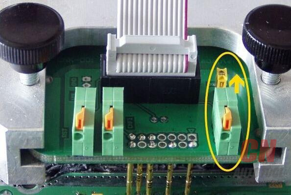
Notice: The adapter switch must be set to ON as shown in the picture:
Connect the ribbon cable 14P600KT03 to the adapter and the Tricore module;
Remove the bridge before re-installing the ECU on the vehicle.
♦ Direct connection
Material needed:
Infineon Tricore module 14P600BTLR
AC Adaptor 1400SWALIM
Cable 14P600KT02
Solder wire
Solder a wire on pin Boot shown in the picture:
Connect the Tricore module 14P600BTLR to the tool, the AC Adaptor 1400SWALIM and the cable 14P600KT02;
Connect the cable 14P600KT02 to the ECU connector according to the pinout below:
Pin Color Description
Pin 42,67 Red +12V
Pin 74 Black Ground
Pin 59 White CAN-H
Pin 43 Green CAN-L
Soldered wire Gray with alligator clip BOOT
Remove the soldered wire before re-installing the ECU on the vehicle.
Step 2: Select the right plug-in;
Step 3: Make a backup copy or read and write the ECU
How to Backup data with K-TAG master:
To make a full backup containing all data of the memories on the ECU:
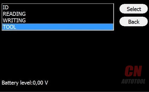
Select Tool:
Select Backup Read:
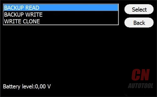
To rewrite the backup file, and so restore the ECU to its original conditions, select Backup Write
from Tool menu.
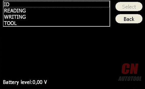
How to Read and Write Ford ECU with KTAG clone on CnAutotool:
Select Reading to read the file containing the maps for engine control.
Select Writing to write the modified file.
Enjoy!
Leave a Reply